Compressor Building Ventilation
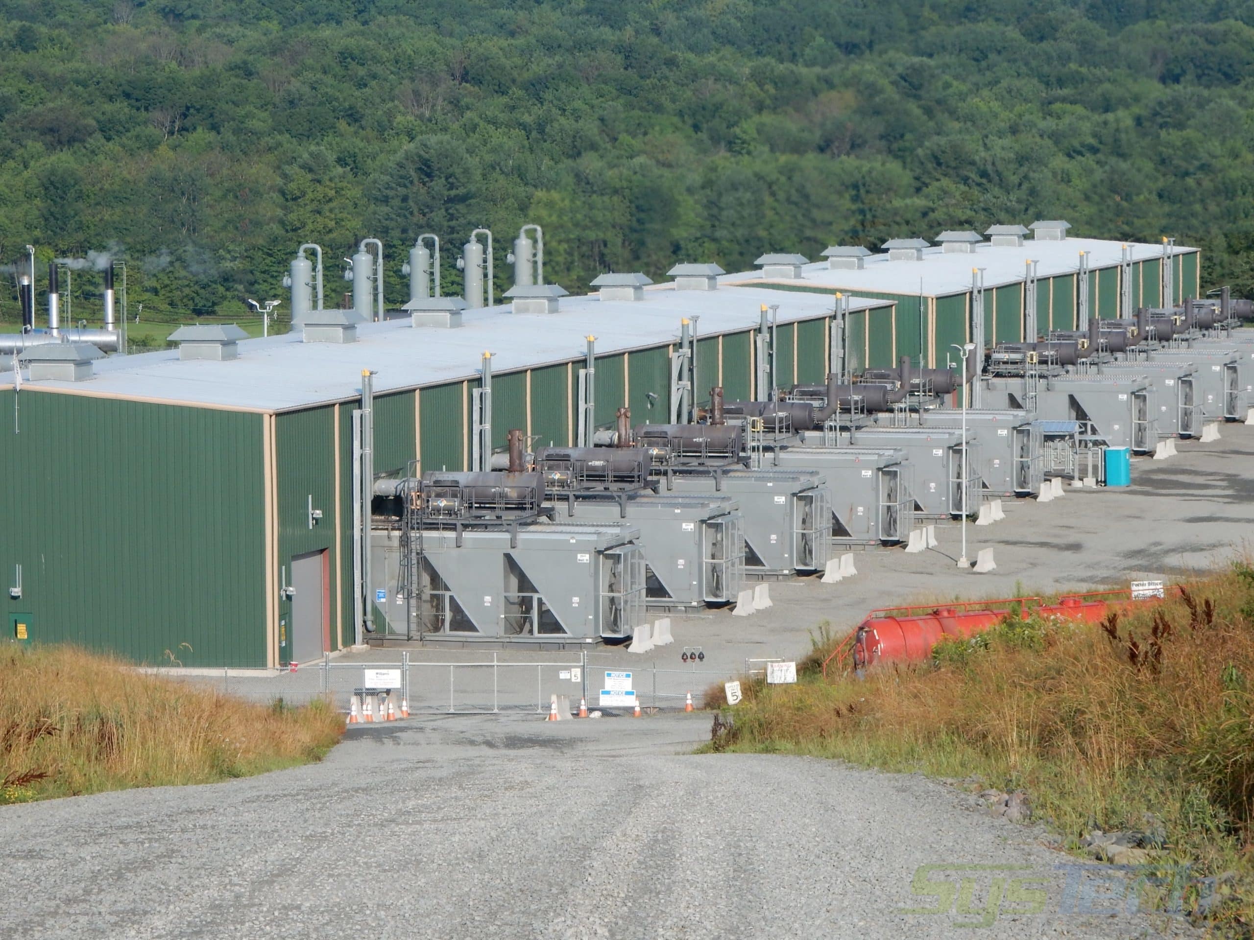
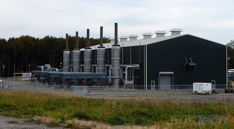
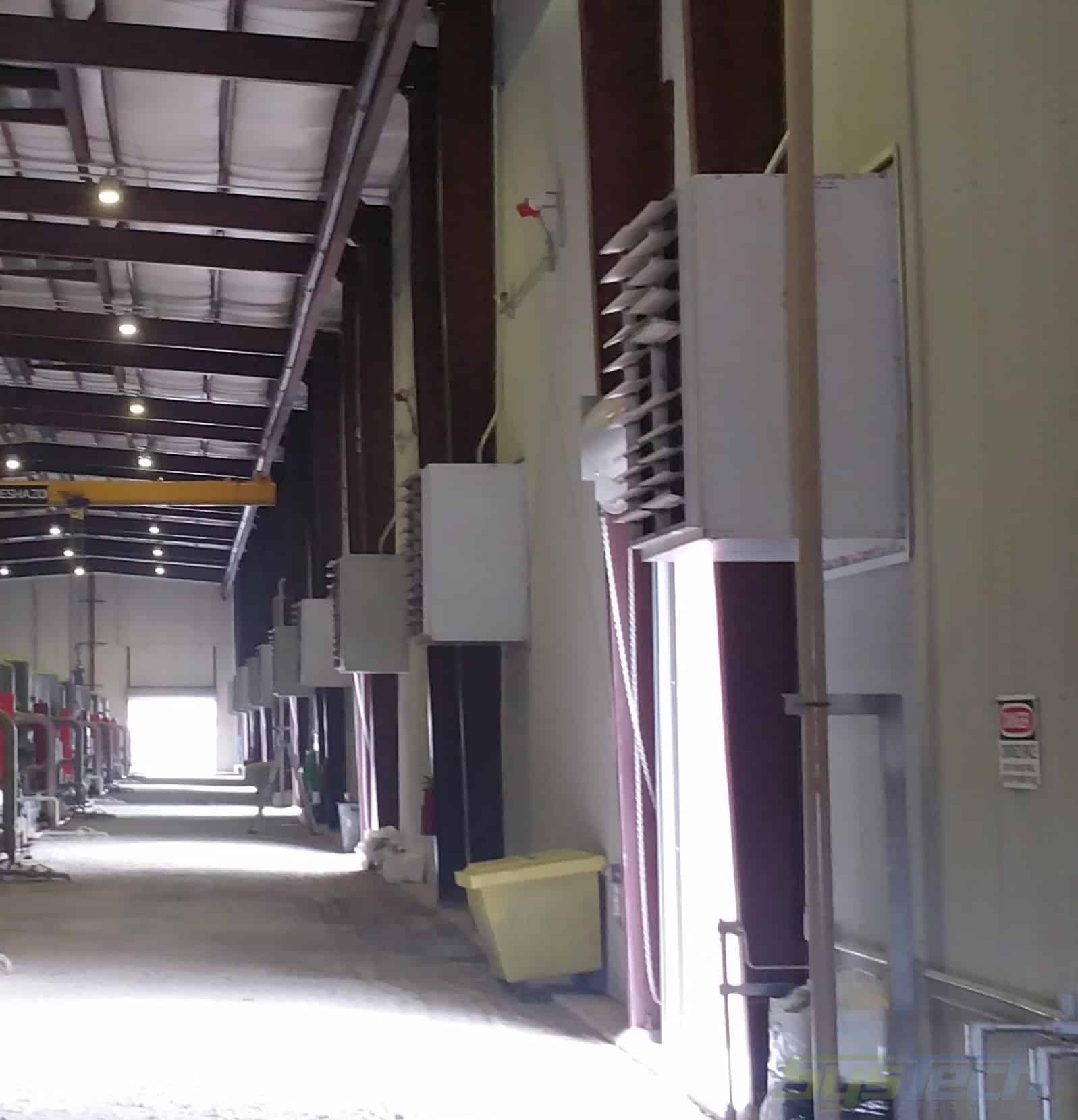
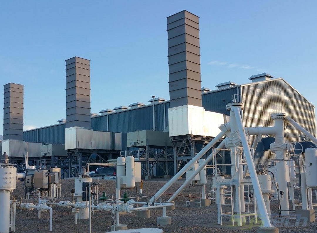
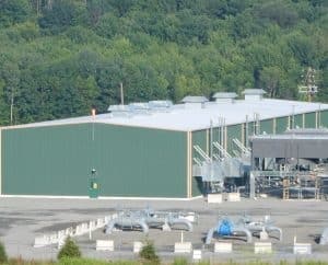
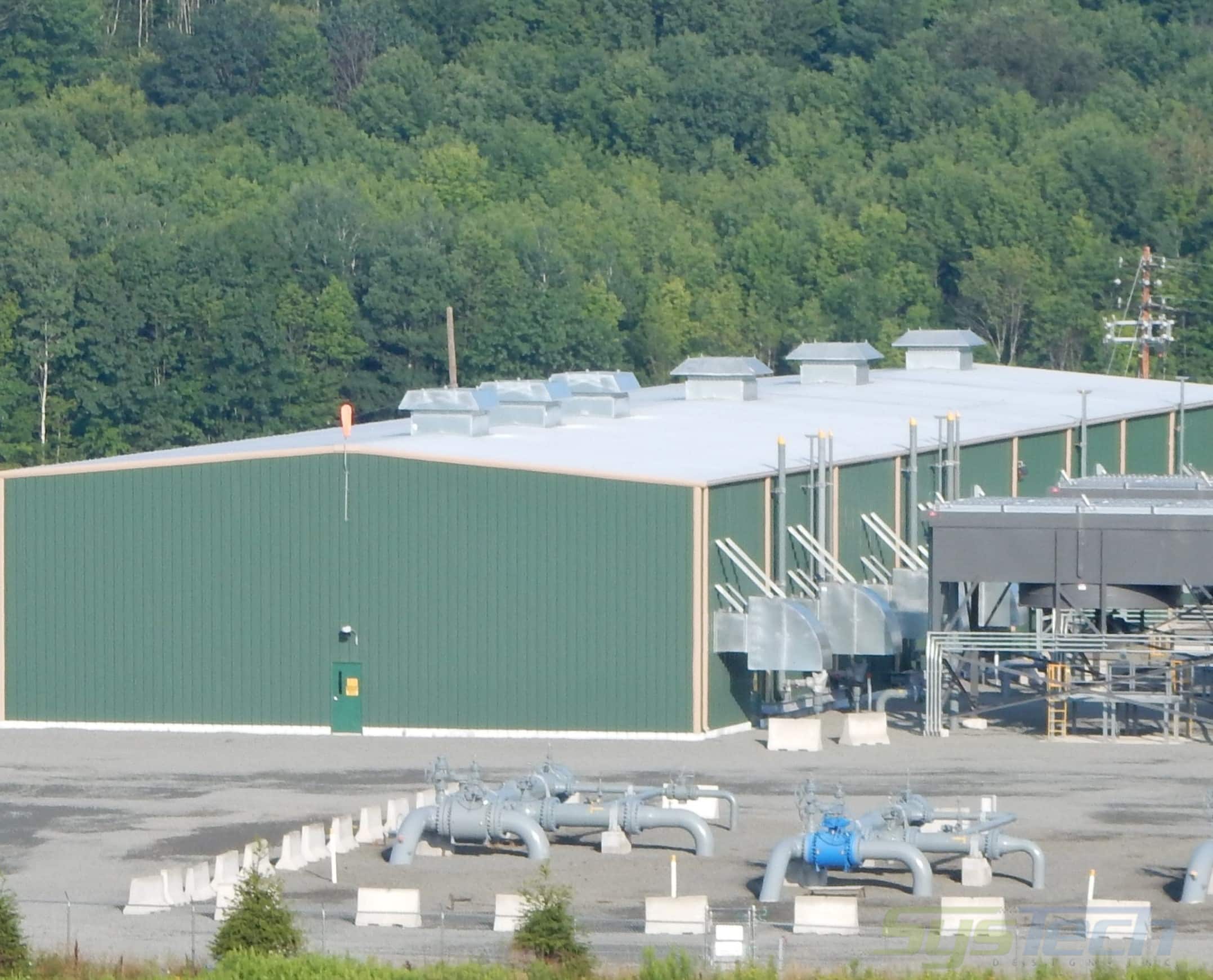
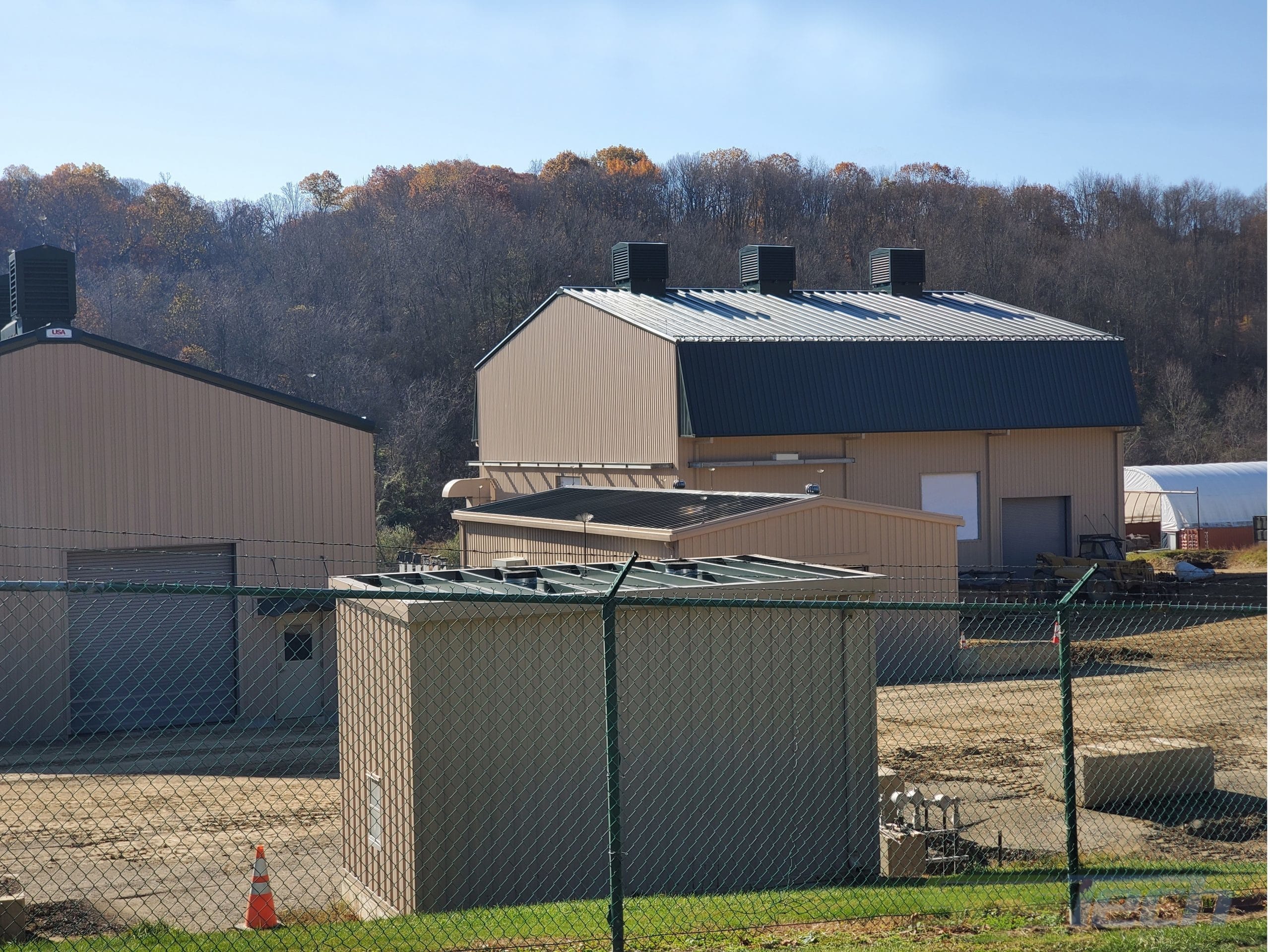
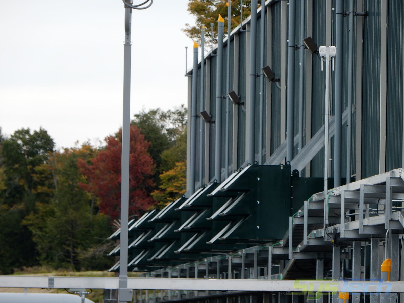
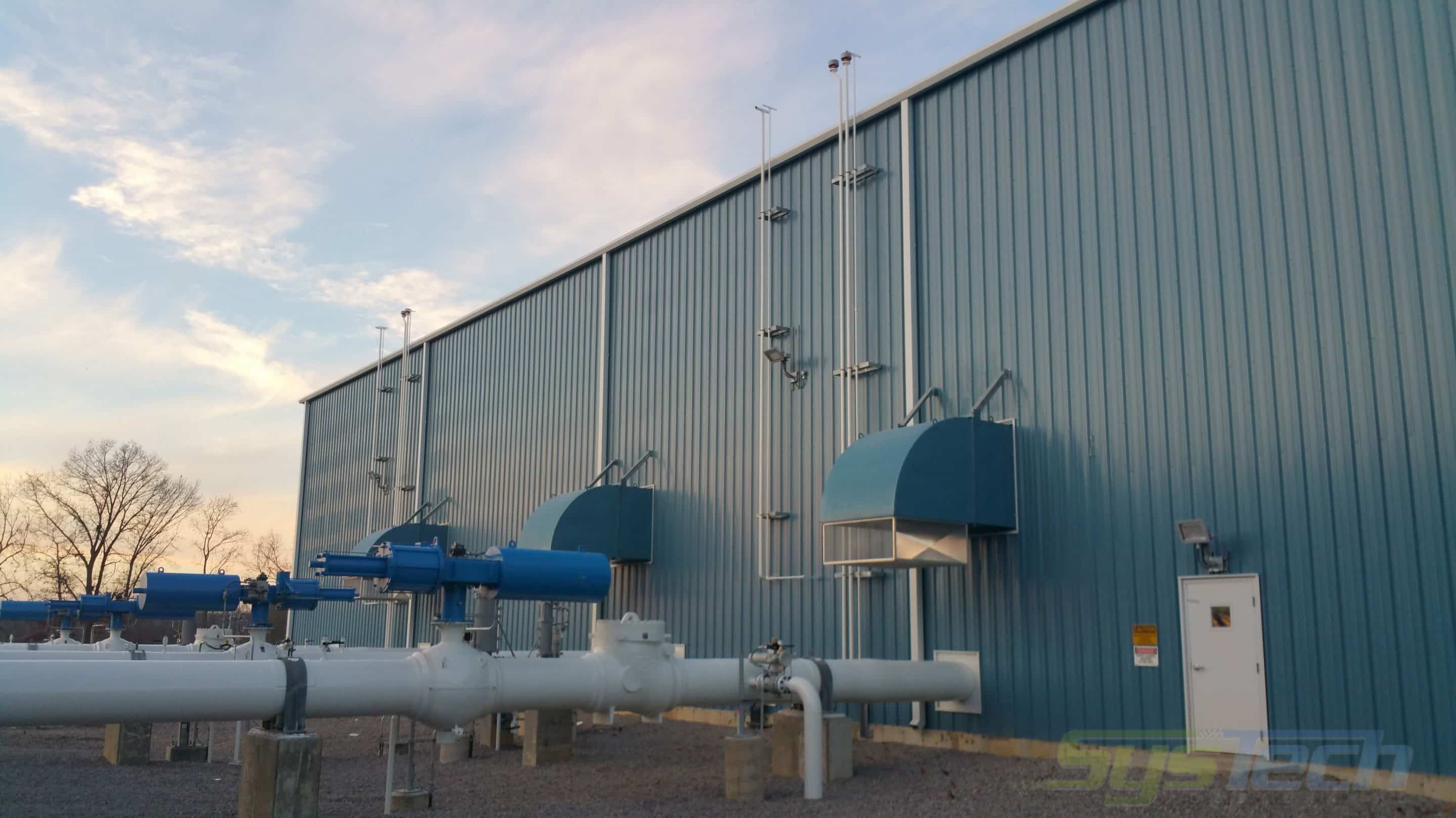
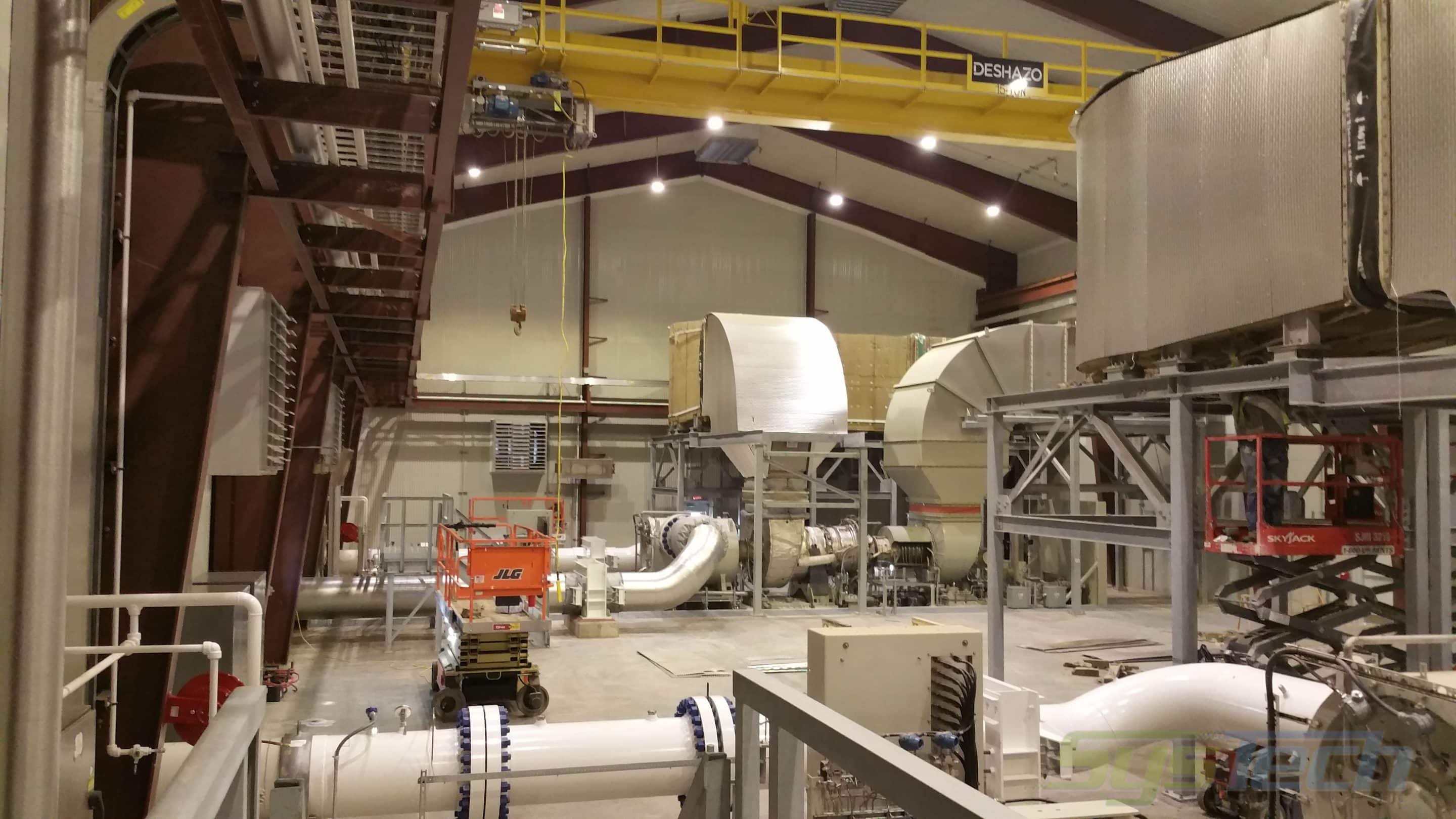
The energy revolution and the evolution of hydraulic fracking to extract natural gas reserves from shales and other tight-rock formations require transport of the collected shale gas from the well sites and drill pads for processing. Compressors used to move the shale gas are housed in on-site metal buildings. Compressor and associated buildings within the facility take a two-fold approach to proper ventilation, heat relief, and noise attenuation. These ventilated structures require both steel building ventilation systems and acoustic building ventilation systems and include Compressor Buildings, Auxiliary Buildings, Office/Warehouse Buildings, Air Compressor Buildings, Meter Buildings, Generator Buildings, and MCC Buildings.
For the most part, fans are used in various configurations to move the air through the building and create a ventilated habitable space. These air movers with associated options have evolved from custom products to standard model configurations.
Compressor Building Ventilation Design
Design considerations include:
- Air changes per hour (ACH) – Specified by Consultant or 12 ACH default
- BTUH equipment heat rejection – per Specification
- Solar loads – Minor issue but included in calculations
- State and local ordinances
- Environmental considerations
- Interior equipment noise
- Permissible Noise Levels (PNL)
- Site location – Weather conditions need to be considered
- Potential of hazardous gases- Placement of fans and designed purge cycle
- Available power
Oil & Gas Facility Ventilation Terminology
Air Filter Box – Filter boxes, side access, or front-loading, with multi-stage replaceable filters, added to remove airborne contaminants from entering buildings and affecting critical components.
Air Handling Unit – Custom designs based on heating and cooling needs, explosion rated where applicable, and up to 4-inch double-wall construction for noise attenuation requirement.
Custom Control Panel – Designed to control various functions of the ventilation system, normally encompassing a thermostat or LEL input, fan motor starters, and rated for use in EXP environments.
Cooler Fan Silencer – Silencers designed to mitigate noise from large, compressor coolers, imposing less than 0.1’’ static pressure.
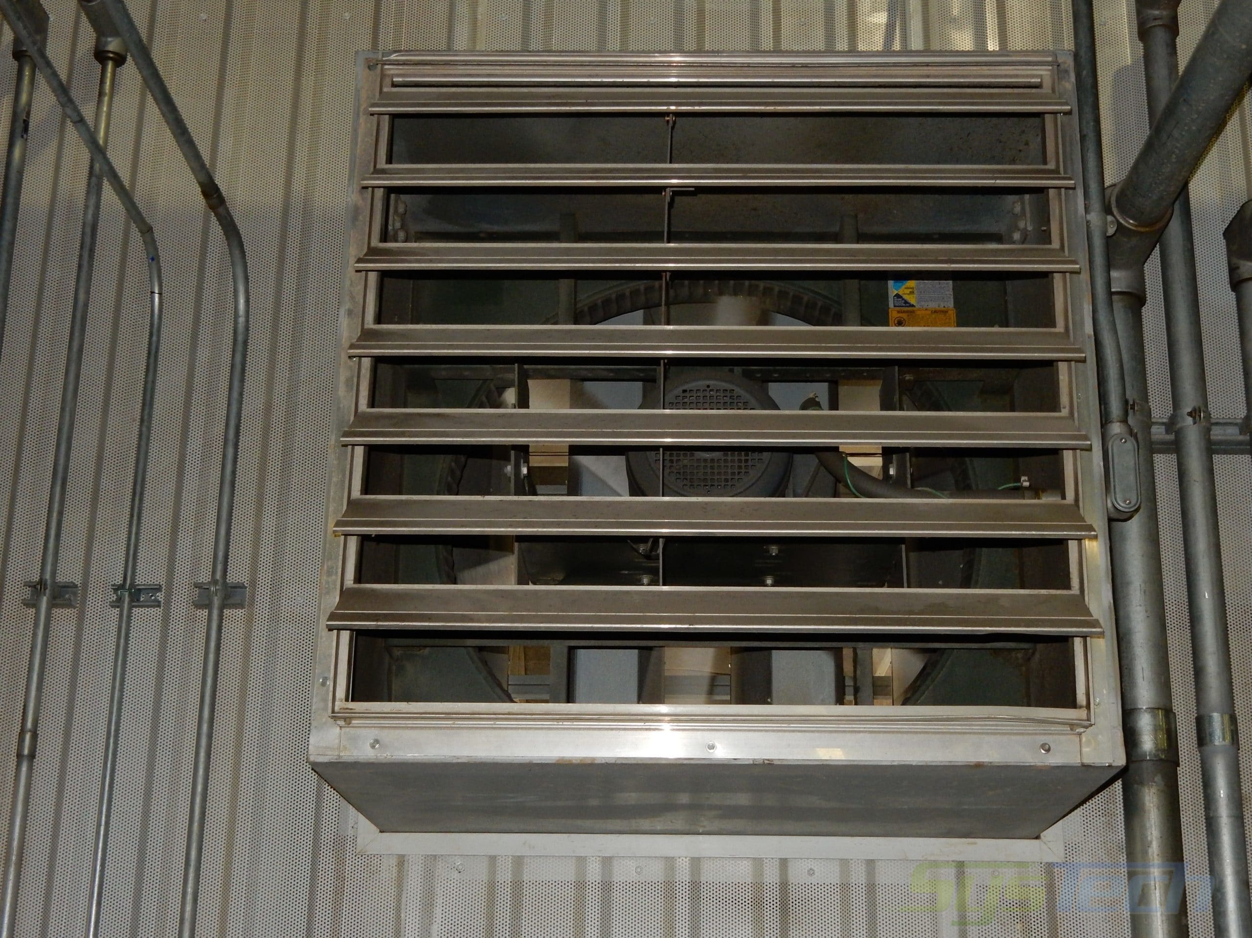
Dampers – Aluminum multi-blade backdraft or volume control designs.
Gravity Backdraft Damper – Airflow operated gravity dampers are normally closed and open when the fan starts up and shuts when the fans are not in operation.
Motor Operated Damper – Dampers operate with an electric actuator and open and close on demand or by a spring-loaded design.
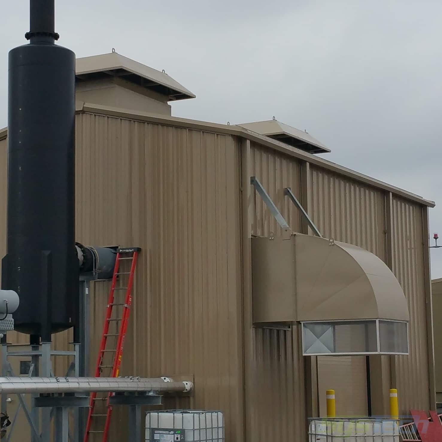
Duct Silencer – Duct sections on inlet or outlet of a fan or air handler, acoustically treated to reduce breakout noise.
Exhaust Fan – Wall or roof-mounted exhaust fans are direct driven with adjustable aluminum props.
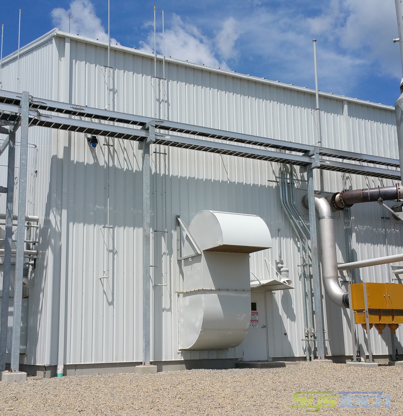
Fan Silencer – An attenuator designed to mitigate escaping sound from both ventilation fans and the excessive sound produced from internal equipment during operation. Selected specifically to meet external dB requirements for the site.
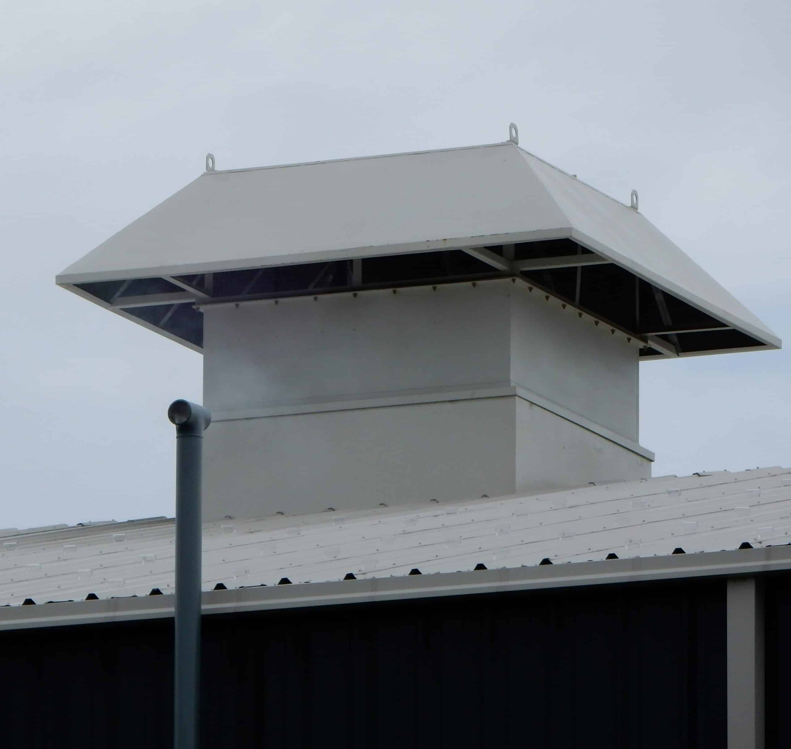
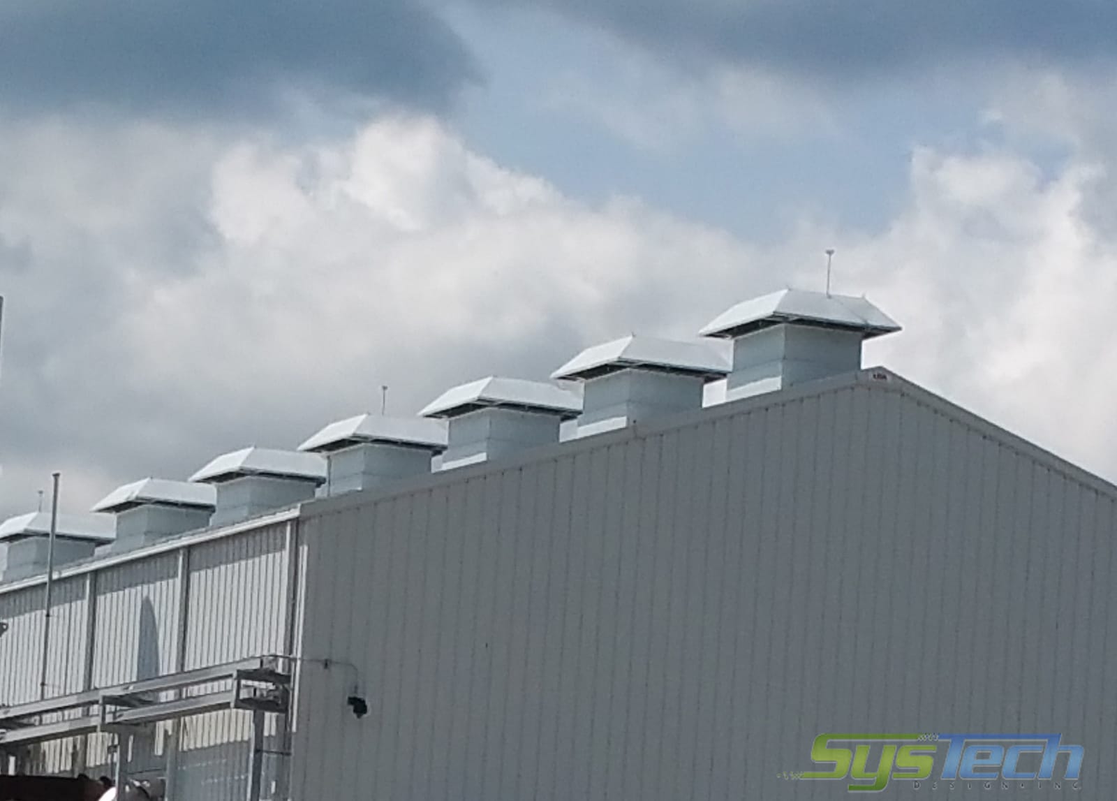
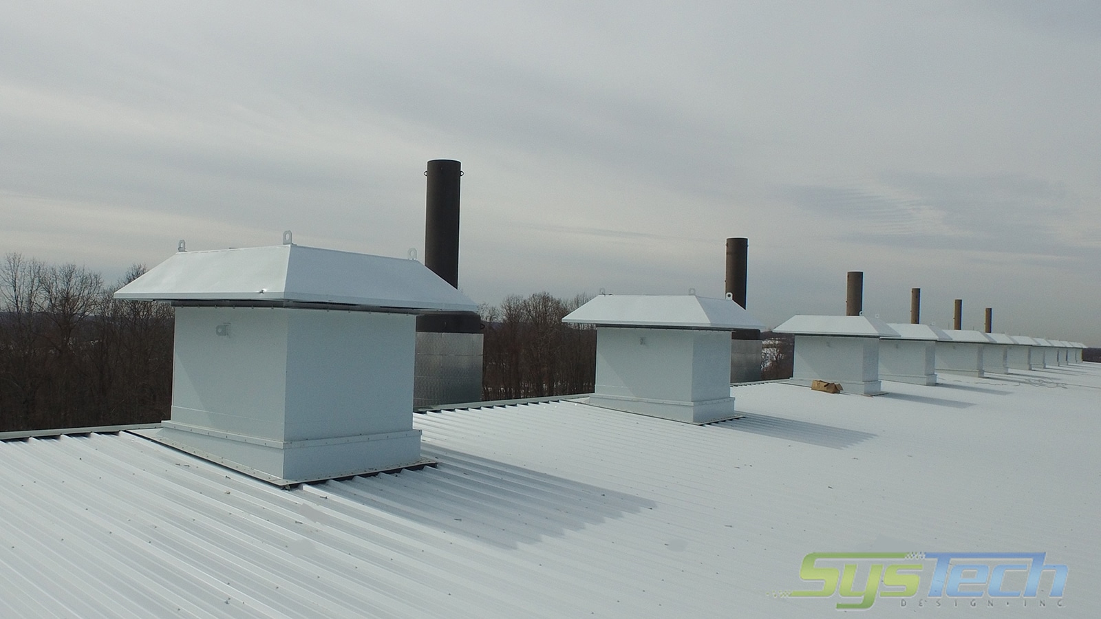
Gravity Roof Vent – Rectangular hoods with bird screen and backdraft damper, with or without silencers. Often referred to as relief air opening or roof-mounted gravity type relief vent.
Hoods – Low velocity designs to prevent snow and rain entrainment.
Acoustic Hood – Weather hoods can be lined with acoustic material for noise mitigation.
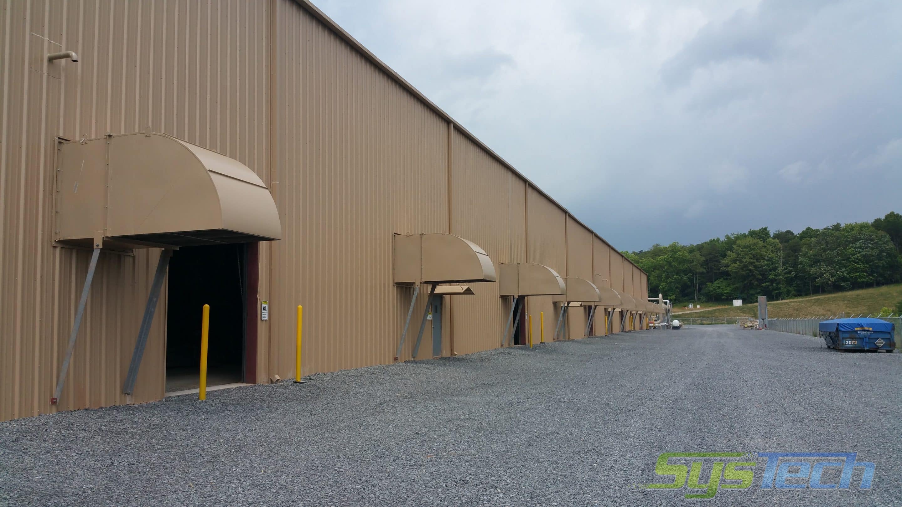
Weather Hood – Wall supply and exhaust fans are protected against rain and snow with a 90° rain or weather hood. “S” shaped or “gooseneck” hoods are a frequent option. Roof-mounted exhaust fans have a rectangular all-welded industrial duty hood design. Bird screen or insect screen are available options for these hoods.
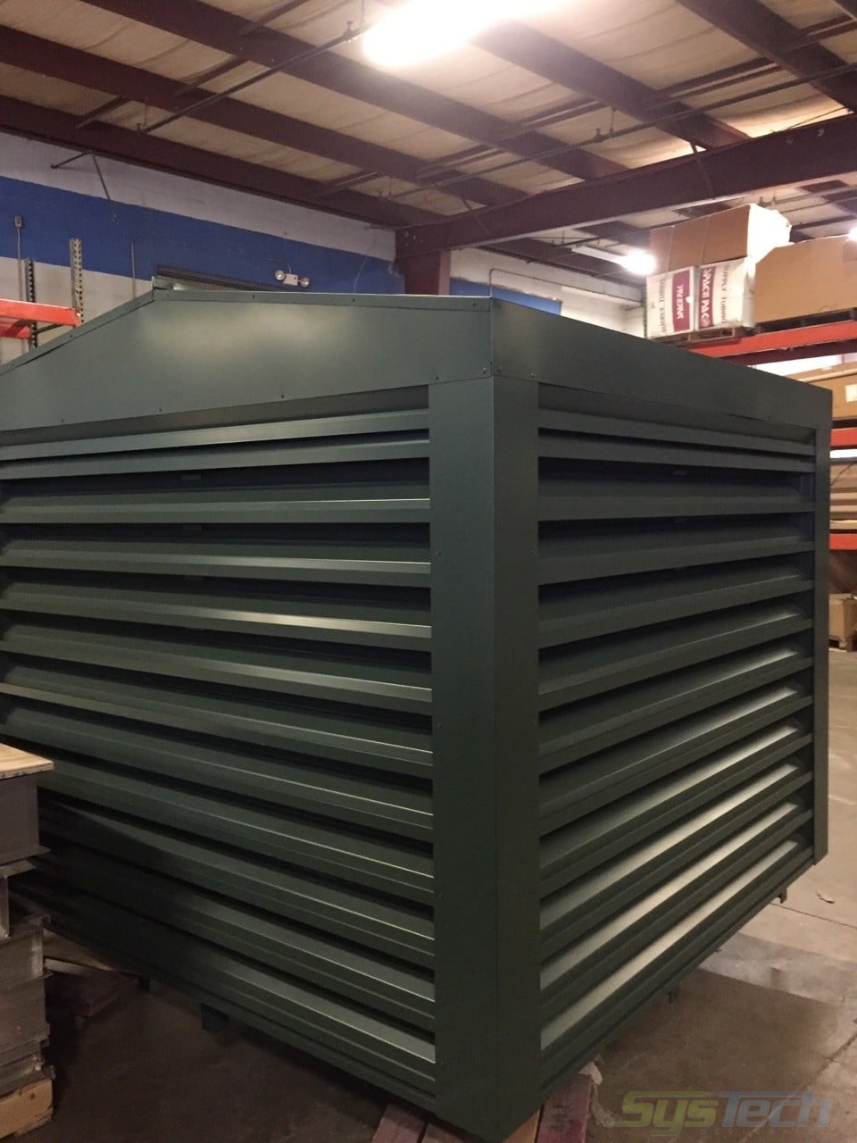
Louvers – Extruded aluminum multibladed designs for all wall openings.
Acoustic Louver – Louvers having fixed blades with acoustic media selected for specified IL’s to mitigate internal noise escape.
Rain Louver – Selected to minimize the entrance of rain with drainable type blades in fixed or adjustable design.
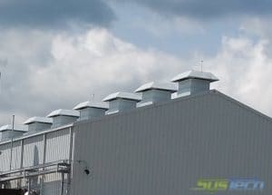
Powered Roof Vent – Roof-mounted exhauster with hood, backdraft damper, and silencer. Might be referred to as an induced ventilation fan.
Purge Fan – With a gooseneck hood configuration to immediately remove heavier than air gases at the floor level used in conjunction with the LEL gas sensor.
Ridge Vents – Continuous vents mounted on the roof peak for heat relief, with throats available from 9 to 36 inches in width.
Acoustic Ridge Vent – Standard ridge vents lined with acoustical cladding to reduce sound escape.
Silencer – Silencer or attenuator, positioned on all building openings, custom-designed to meet noise reduction specifications.
Supply Fan – Wall mounted supply fans, direct driven with adjustable aluminum props. Sometimes referred to as “forced ventilation fan assemblies.”
Unit Heaters – For cold weather conditions, where supplemental heat is required.
Catalytic Heater – Designed for use in hazardous locations, gas-fired with chemical reaction pads producing infrared heat.
Electric Heater – Available up to 35 KW per heater for hazardous area configurations.
Gas Heater – Standard and explosion-proof units available (CL1, D2, GD) including propeller fans for forced draft design.
Hot Water Heater – propeller type unit heaters utilizing building hot water heating system. Available in explosion rated construction.
Infrared Heater – Unit tube heaters are available for use in personnel areas.
Variable Frequency Drive – For supply or exhaust fan airflow (CFM) and static pressure (inches WG) modulation.
Compressor Building Ventilation System Configurations
Wall Supply Fans with Gravity Ridge Vent – A push system where the building is pressurized and accumulated internal heated air is expelled through the roof opening.
Wall Supply Fans with Powered Roof Exhaust Fans – A push-pull system where outside air is drawn into the building and the roof exhausters draw the heated air out of the structure.
Wall Openings and Ridge Vent – Completely unpowered design using wind and the internal heat gradient within the building to naturally initiate air movement and ventilate the structure.
Louvered wall inlet openings with Powered Roof Exhausters – A “draw thru” system where the roof exhausters are the primary air mover creating a negative building pressure and evacuate the building contents.
Purge Cycle Fans – Where the potential for explosive or asphyxiating gas accumulation is present and needs to be addressed, fans are positioned to immediately evacuate building contents.
Internal Unit Heaters – Where supplemental heat is required unit heaters are strategically positioned within the facility.
Packaged Ventilators for Oil & Gas Facilities
Responding to the need, SysTech has developed a series of standard units or modules with multiple options to fit a proper ventilation system into a compressor building. These Lo-Noise™ Modules are available in both heavy-duty and light-duty construction. The direct-drive aluminum bladed adjustable pitch fan, however, is a standard feature in both cases.

