Compressor Station Ventilation

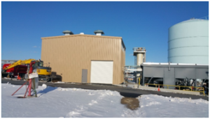
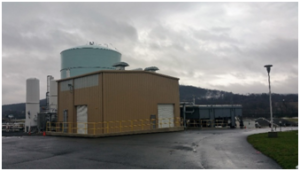
The tan steel building shown, houses both compressors with compressor coolers located outside.
An energy services company approached SysTech with the task of designing and supplying ventilation for a new compressor building at their PA facility. SysTech was selected based on a history of ventilation system designs in over 50 midstream stations. The plan was to build a new compressor building, updating a previous design to add a 2,000 HP nitrogen recycle compressor in addition to a smaller 250 HP reciprocating natural gas compressor. The station is a ‘Mid-Stream’ station where Natural Gas is stored until required by market demand.
In addition to the Natural Gas compressor system, the nitrogen system is the main circulation driver in a closed-loop refrigeration process, a modified Carnot Cycle. This nitrogen compressor is a flooded screw design that has a power rating of 2,000 HP. It compresses nitrogen from 5-10 psig to 250 psig. With these extreme pressures, the gas is expanded across a turbo-expander to generate a low pressure cold refrigerant. This refrigerant is heat exchanged with a warm natural gas stream to liquefy it for storage.

The two hoods located on the roof constitute the exhaust fans of the Rapid Purge System.
The goal of the ventilation project was two-part: heat removal from the building and emergency purging of the building if an upset condition occurred. Compressors are heat-generating equipment; they output high BTUHs of radiant heat. When temperatures exceed interior space design limits, the expensive compressor units are exposed to excessive wear and reduced equipment life. In addition to the compressor generating heat, the solar loads on the building add to the interior heat loads. The first part of our design addressed these temperature issues. The second part was to design an automated ‘hands-off’ system to deal with the potentially hazardous concentrations of natural gas and nitrogen that could develop inside the building. This “purge system” was required and approved for compliance by the Federal Energy Regulation Commission after implementation.
Steel Building Ventilation Design
Industrial ventilation using the air change method is either a passive (aka “gravity” or “natural”) or an active design. The heat removal portion of our project was passive. Passive design relies on buoyancy driven ventilation based upon the differences in density of the interior and the exterior air temperatures. A twelve (12) inch throated static ridge vent was positioned at the ridgeline and two (2) intake louvers installed along the building walls to creating a low-to-high air path, allowing heat to escape high in the building and fresh, cool, ambient air to replace it at ground level. Typical operation consisted of passive intake louvers to supply clean, outside ambient air to the space. Intake louvers were placed low on the building walls and were manually adjustable, allowing closure during the cold-weather months.
Handling Explosive or Asphyxiation Gases in a Metal Building
The “purging” portion of the system was active ventilation and was designed to evacuate the interior volume of the building should gas levels exceed allowable concentrations (25% LEL). Both the natural gas and nitrogen compressors handle gases that are lighter-than-air and pose a potential asphyxiation hazard to personnel inside the building. Gas sensors were placed at seven feet off floor line, above normal breathing zone height and set to actuate the fans whenever dangerous levels of Natural Gas or nitrogen levels were detected. When this condition occurred the motorized dampers on the intakes of the roof fans would open and begin exhausting the building interior at the rate of 24 air changes per hour, roughly exchanging the air every 2.5 minutes! Once gas levels were reduced to an acceptable level, the sensors deactivated the fans and the dampers closed to a static position.
Equipment Selected to Meet Safety Concerns
A safe ventilation system requires that individual equipment construction is selected when working in hazardous locations. The Natural Gas present required a Hazardous Area Classification of Class 1, Division 1, Group D rating. The 2 HP motors on the exhaust fans were selected as NEC Explosion-Proof construction, as were the damper actuator motors. Similarly, the spark resistant fans were selected as AMCA B construction with aluminum props.
The system was designed to be low maintenance, requiring minimal inspection from plant personnel, resulting in an unmanned site. The station has been operating autonomously since late 2014, allowing the client to focus their efforts on other important tasks.
We strive to design and provide ventilation that is efficient and worry-free. Call us at 800-456-9460 to find out how we can create the best system for you.


